Finger on the pulse

Aprilia Caponord ETV1000 Rally-Raid. Speedometer pulse from the rear-wheel sensorWhile the wrist is healing nicely on light-duties and (thankfully) out of the heavy and restrictive cast, I’ve had a chance to play with the idea of an active cruise control for the Capo. An active system will adjust the throttle automatically to maintain a given speed even as the road rises and falls unlike a passive system which is nothing more than some form of throttle locking mechanism.

Arduino cruise control sketchThe system I’m thinking about will, when all parameters are met (speed, revs etc) lock onto the chosen speed when the ‘Set’ button is pressed. The microcontroller will then look at the error between the chosen speed and actual speed and adjust the throttle as neccessary to try and maintain the error at zero – this is done using PID (proportional-integral-derivative) in the controller. If cruise is stopped (operation of brake or clutch) or the PID error goes beyond a pre-determined maximum (high gear on a steep hill for example) the requested speed is stored and can be re-activated by pressing the ‘Res’ume button. And while in cruise, the speed can be adjusted in 1Kmh increments by using the same two buttons, now working as ‘Acc’elerate and ‘Dec’elerate. That’s the theory anyway!

Aprilia Caponord ETV1000 Rally-Raid. Opto-isolated and cleaned Speedometer input signalInputs

  • Power – 12v on/off switch
  • ‘Set/Acc’ &Resume/Dec’ buttons – 12v
  • Front and rear brake light switches – 12v
  • Clutch lever switch – 12v
  • Speedometer signal from the dashboard (output on pin 14 of the 16-pin connector) -12v square wave 85% duty cycle frequency modulated
  • Tachometer signal -12v square wave 50% duty cycle frequency modulated.

Honda GL1800 Cruise ServoOutputs

  • Two colour LED for power, cruise engaged & error codes – 5v
  • Motor drive signal – 5v PWM to motor control board.

To date the inputs and safety stuff has been written and from the tacho/speedo signals it’s calculating what gear the bike is in pretty quickly, but I’m sure it can be speeded up …… I just need to learn more programming! The operating parameters I’ve decided on are:

  • Cruise enabled between 50Kmh and 160Kmh (30mph – 100mph)
  • Cruise enabled between 2,750rpm and 6,000rpm but might change the lower limit to 3,250rpm in 6th gear
  • Cruise enabled in 4th, 5th and 6th gears only.

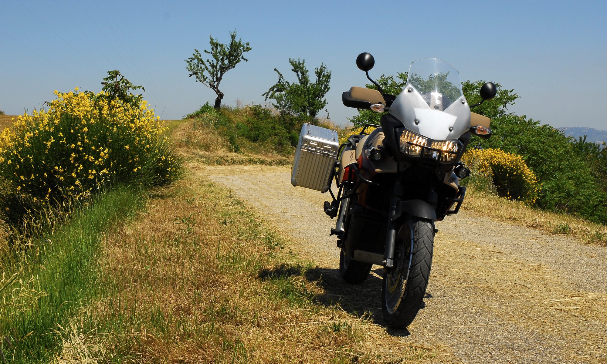
At the end of the day, I just want a system that will give my old worn out wrist a rest at motorway speeds on the run between Italy and the UK, taking into account the (very!) variable speed limits and ascents/decents especially through Switzerland. If it can do that I’ll be a very happy bunny indeed.

Of course this is all well and good, but I’ve got to get all the bits talking to each other first and make it robust enough for long-term and safe use on a motorbike ….. the problem is that in amongst all this enthusiasm my wrist still has a way of letting me know who’s really in control while swanning around on light duties!


New ‘Lockwood’ inlay fitted at last

Right indicator repeaterOn 4th February Jan came back home with a suitcase fair groaning with all manner of goodies. The most eagerly awaited though, was the pair of new inlays from Lockwood International Ltd. So first impressions?

Excellent! From the textured material to the bleed-free printing, from the fit to the light-transmission …. everything was exactly as I’d hoped. The first thing I did was pop one onto a waiting chassis/board and turn on the lighting – did the text and colour match the light channels? Again, perfectly. Now I could relax, prepare the new chassis and get ready to fit one permanently to the dashboard. To fix it in place I decided to use a general-purpose spray adhesive and did a trial run on an old chassis/inlay to make sure it would be suitable. Everything seemed fine and it was certainly good experience to do a dummy run.

Making sure the chassis was grease and dust free was essential, then masking off the light-channels, mounting pegs and anywhere else I didn’t want spray glue to go! A couple of thin coats of adhesive were applied and the inlay fitted 10 minutes later to allow time for the solvents to evaporate. Perfect! It was now ready to be fitted to the circuit board, but first a couple of modifications to the board/processor circuits.

First the eeprom file needed to be updated for the Futura speedo/tacho, then the code in the microcontroller needed updating for the different (voltmeter) needle calibration. At the same time a couple of modifications were made to the circuits based on insights I’d picked up about Arduino boards from the Internet, also the auto-dimming circuit was finally added for the variable back-lighting, a bit of tweaking with the code – and it was all ready to be refitted to the Capo.

So there I was …. on a wind-swept but warm Sunday morning, dashboard in hand and about to see the fruits of a few months work finally come together on the bike. No doubt the code for the auto-dimming will need fine-tuning, but that can be done without removing the dashboard again – and that’s the line in the sand, right there. Once fitted, I shouldn’t have to remove them again anytime soon …. and that’s a great feeling!

I think that about now would be a great time to pause and say thanks to a few folks who have helped me keep the momentum in this little project. Firstly Jan for her patience and for lugging stuff across the continent for me, to Andy (beasthonda) for bouncing ideas around with me and his interest in the project, to Arvdee in the USA without who’s generous donation of a Futura inlay I wouldn’t have had a template.  Last but not least, Clive from Lockwood International for putting the proverbial icing on the cake – thank you all!!!! 😀

Moving along nicely

Just got this photo from Clive over at Lockwood International in the UK, the nice folks who have made my new inlays for the Caponord dashboard. I’ll write more when they arrive …… I can’t wait!!

RST Futura based inlay with voltmeter and left/right indicator repeaters

  • Back-lit voltmeter within the tachometer
  • Left & Right indicator repeaters
  • Red-line raised to 10,000rpm to match ECU setting
  • Side-stand lamp is now where the unused ABS lamp was
  • Funky Aprilia lion instead of boring old ‘aprilia’ text
  • ‘magneti marelli’ logo removed …. well they didn’t design this one!

Tacho/Voltmeter live on the Caponord

Up and running at lastPhase 1 is over, Phase 2 begins …….. yes, the reworked dashboard with voltmeter/tacho and fade-in/fade-out auto-dimming backlighting is off the workbench and finally onto the Caponord. I know it doesn’t look too inspiring at the moment, but it is only a prototype unit for development. The white tacho face is simply a temporary inlay printed on a piece of A4, so it better not get wet!

Arduino Uno V3Inside the box lives an Arduino Uno with a homemade interface board that switches and adjusts the signals to/from the dashboard as required. The single connector plugs into an additional fused loom that runs to the battery positive terminal. I’ve tried to build in safeguards against under/over voltage, battery disconnection and reconnection spikes and its own failure with regards to how the dashboard functions, hopefully most if not all eventualities have been covered …. fingers crossed!

The little grey box .... I’ll run this setup for a while and try to iron out any other issues as they crop up, but what then? Well Phase 3 has already started in parallel with Phase 2! A new microcontroller board that uses the same chip, but with a footprint that is an astonishingly small 8% of the Uno has been ordered. Not only is it small, it also loses the peripheral bits and bobs that I don’t need – and that means much lower power consumption. I’m really hoping to get the whole thing inside the dashboard case if possible, but the worst case scenario will mean a small box fixed directly to the back of the dashboard – so no wiring loom or bulky connectors!

Where the ideas originated ..... the Kwak GT & GPZ's of the 1980/90 eraAs well as getting the inlay reprinted with the added voltmeter graphic, I’ve also decided on a little  re-arrangement of the existing graphics and functions. For example, why oh why is a ‘side-stand’ light prime-center of the display when it already has a safety circuit to stop you riding away with the stand down? ….. Magneti Marelli over-egging the pudding I think.

So the side-stand is moving down to the (unused) ABS lamp spot, the low-fuel then moves up to the side-stand lamp and the low-fuel light then becomes the right-hand indicator – as it should have been all along. Yes, a turn repeater for both left AND right hand signals!!!

Left AND right turn repeater lamps!

With all this in the pipeline, I can now source a decent place to have the new inlay card made. I’ve spoken to a couple of companies in the UK already, but I’ll keep looking around for a little while longer …….. do you know anyone you can recommend? If so, I’d like to hear from you.

 Last but not least, here’s another short piece of video with the panel working on the bike.


Dashboard upgrades

Evening folks, I thought I’d share this with you as the nights start to draw in and riding gives way to winter tinkering.

I mentioned over on the dashboard page about the upgrades hopefully working by spring next year. Well some of them have come along in leaps and bounds, so I took a snippet of video so you can see a dashboard work-in-progress strutting it’s stuff on the workbench. OK, I know that there’s no voltmeter markings on the inlay yet, just use your imagination for now! It’s actually showing 12.4v ……….

Now while I’m waiting for an oscilloscope to miraculously appear, I’ll leave the board bench testing for a while to see if the code or controller breaks, then fingers crossed, it’s on to the auto-dimming back lighting instead of the three fixed settings of useless, mostly useless and acceptable.

A little light circuit training

Aprilia Caponord ETV1000 Rally-Raid - Dashboard large LCD panelOn a previous post I mentioned a visit by Mike081. During his stay I said that I’d like to get hold of another instrument panel at some point, so I could look into the circuit and programming in more detail. It just so happened Mike had a board lying around and he promised to sent it over. Well, true to his word, a Mk2 Caponord board was sat on the post-box when I got back home the other day. Cheers Mike!

First, I made a stand to support the little beauty while I prodded and poked around withAprilia Caponord ETV1000 Rally-Raid - AutoCAD circuit layout my trusty multimeter. The next job was to try and fix it! The board had a couple of problems, a high resistance track and faulty regulator but nothing too taxing. Next up, I photographed the front (high resolution pic here) and back, then imported them into AutoCAD and started the tedious task of unravelling the tracks and components (click on pic).

Next up, the EEPROM. The little memory chip that contains settings and data relevant to the running of the board and recording of mileage and trip.

Aprilia Caponord ETV1000 Rally-Raid - dashboardTwo AF1 forum members – Michele (MCR) and Andy (Beasthonda) have been forefront in unravelling the data on the chip and how it alters the way the board works. The bottom line is that instrument panels from both the Caponord and Futura can now be reprogrammed in various ways and used on either bike. This also means that the ability to safely recover boards that have reset to factory default is now possible.

I’d like to thank both Andy and Michele for including me in the email exchange and for sending data and documents so I can better understand the particular settings for each bike – Cheers gents, you’re the best!

So this week I’ve experimented with the alternative settings and sure enough my little board has changed from Caponord to Futura and back and dabbled in metric and imperial measurements and even been a hybrid – Caponord with Futura LCD display and Speedo/Tacho calibration.

Aprilia Caponord ETV1000 Rally-Raid - dashboard